Local STO on MKD-N
General information (local STO)
The STO safety implementation on the MKD-N is certified. The safety circuit implementation used for the safety function "Safe Torque Off" in the drive is suited for SIL 2 according to IEC 62061 and PLd / CAT3 according to ISO 13849-1.
There is one STO input on X26 and one STO-Status output on X24 for every drive axis.
Enclosure, wiring (local STO)
|
|
Avoid pollution of the connectors with conductive obstacles Observe the required ambient conditions. |

Overall environment notes and wiring requirements: Enclosure, wiring.
Maximum cable length for safety relevant I/Os and for the 24 V supply is 30 m.
Technical data and connection (local STO)
|
|
The local STO input is not compatible with IEC 61131-2. Connector X26 ensures requirements of pollution level 3 according to IEC 60664-1. |
|
STO inputs |
|
|
STO-Status outputs |
|
Pinout connector STO input signals
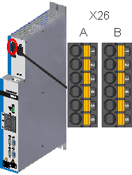
|
|
Pinout connector STO output signals
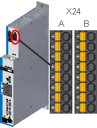
|
|
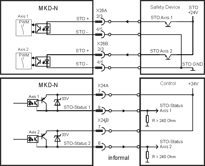
Wiring diagram STO Signals, example
Environment notes and wiring requirements: Enclosure, wiring.
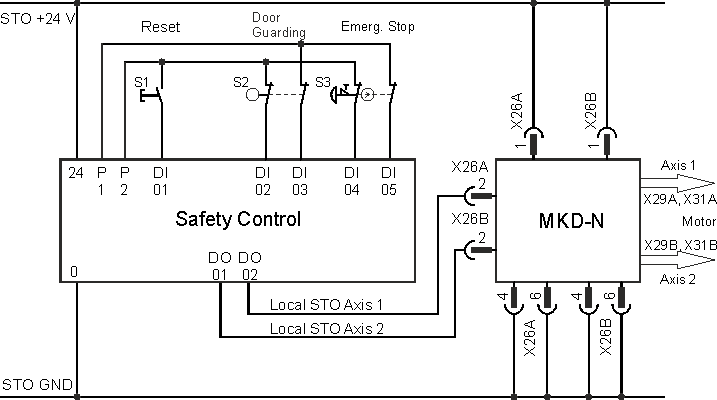
Application example (local STO)
The sample application below shows door guarding and emergency stop, controlled by a safety control to switch the local STO inputs of a dual-axis MKD-N drive module to SIL2, PLd. Both axes strings are switched independently.
|
|
Kollmorgen KSM modules cannot be used. |
Functional description (local STO)
The STO input releases the power output stage of the drive as long as a 24 V signal is applied to this input. When the local STO function (Safe Torque Off) is not needed, then the STO inputs must be connected directly to +24 VDC. The function is then bypassed and cannot be used.
|
|
The global STO signals have no influence to this drive. The local STO input on the MKD-N has no influence to any global STO as well. |
|
Local |
String |
Local |
Safety acc. to SIL2 |
Drive can |
|---|---|---|---|---|
|
0 V |
no |
high |
yes |
no |
|
0 V |
yes |
high |
yes |
no |
|
+24 V |
no |
low |
no |
no |
|
+24 V |
yes |
low |
no |
yes |
When STO function is engaged during operation by separating input STO-Enable from 24 V, the connected motor slows down without control.
|
|
|
|
|
Use the following functional sequence when the STO function is used:
|
|
|
It is not possible to perform a controlled brake if the drive STO input is off. |

Functional test (local STO)
|
|
You must test the safe torque off function after initial start of the drive, after each interference into the wiring of the drive, or after exchange of one or several components of the drive. For dual axis modules you must test every axis separately. |
First Method:
- Stop the drive with setpoint 0 V. Keep drive enabled.
DANGER: Do not enter hazardous area! - Activate the local STO function for example by opening protective screen of the drive, (voltage at input STO = 0V).
- The drive lose toque and slows down to zero speed without control.
Second Method:
- Stop the drive with setpoint 0 V, disable drive.
- Activate the STO function, for example, by opening protective screen (voltage at input STO = 0V)
- The drive cannot be enabled.